
How solar power is connected to the grid
Here’s the case study on a 50-MW solar power project connected to the grid by Hartek Power in Andhra Pradesh
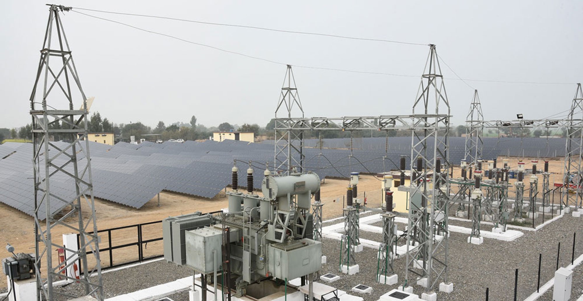
One of India’s fastest growing EPC companies based in Chandigarh with expertise in executing high-voltage turnkey substations and power infrastructure projects Hartek Power Pvt Ltd has successfully connected a 50-MW solar project to the grid in Anantapur district of Andhra Pradesh.
The scope of work of the 132/11 KV substation project, which happens to be Hartek Power’s first one in the state and its biggest in south India, involved complete turnkey solutions and post-inverter works covering the design, engineering, installation and commissioning of the power plant electrification and automation systems as well as pooling stations.
This project was part of a 113-MW order awarded to Hartek Power by a leading developer in October 2016 for solar grid connectivity projects spread across five states including Andhra Pradesh, Karnataka, Rajasthan, Punjab and Bihar.
There were 24 group stations in all. Each group station comprised:
-
- Inverters: Their function was to convert DC power from solar panels to AC power.
- Inverter duty transformers: Their function was to step up the voltage from 11 KV to 132 KV to the main grid.Hartek Power used Schneider-make inverter duty transformers in all the group stations.
- Ring main unit: Its function was to switch off and switch on the circuit. Selection of ring main unit rather than an outdoor breaker was aimed at optimising the design and providing a cost-benefit analysis with special focus on quality and strong technical specifications. Hartek Power used Siemens-make RMU in all its group stations.
- Cables: Cables, an integral part of solar EPC projects, are used to transfer the power from one point to the other. Cable-laying is an important activity, for which it is important to adhere to all technical guidelines. Hartek Power has a dedicated team which specialises in cable-laying so that the system is properly designed.
- Low voltage panels: These are used to give supply to auxiliary items and all panels used were of HARTEK make.
The design team at Hartek optimised the entire group station, designed the entire group station at 11 KV level rather than 33 KV level to give a much more optimised design, which worked well for the customer in terms of cost-benefit analysis. At 11 KV level, the cost of equipment and system goes down, as a result of which a more optimised design is created.
There were 22 group stations of 2.2 MVA and two group stations of 1.1 MVA, bringing the total capacity to 50 MVA. The power from each group station was stepped up to 132 KV and was fed to the main grid via power and control cables. The power from each group station terminated at the main control room at the 11 KV medium voltage switchgear.
The main grid was the termination point at which power was to be evacuated and fed to the government substation. The main grid was designed by Hartek as per APTRANSCO guidelines. The main grid comprised a switchyard and the main control room, where all controls of the power plant were there.
The main grid had two transformer bays and one line bay, and comprised the following major equipment:
Power Transformers: Two each of 25 MVA capacity. The PTR holds the key and it determines the load also. There were two 132/11 KV step down power transformers each in the main grid. The 132 KV was coming from inverter transformer as explained above and its output was 11 KV, which was being distributed across. Hartek Power used Schneider-make PTR in its main grid
Current and Potential Transformers: The most crucial and technical items are the CT AND PT, which play a dual role in the grid for measuring the current and voltage, respectively, and are also used for protecting the capital equipment. If the current or voltage goes beyond the limited value, the relay detects the fault and the breaker breaks the circuit, thus saving the plant from breakdown. The make used by Hartek Power was Mehru.
Isolators: An isolator is fundamentally used to isolate the circuit when a fault occurs. There are two types of isolators, one with earth switch and the other without it. Hartek used Siemens-make isolators in its grid.
Circuit Breaker: The circuit breaker is used to break the circuit when the fault occurs. The gas used in the circuit breaker is SF6 (sulphur hexafluoride). SF6 is extensively used these days as an arc interrupting medium in circuit breakers ranging from 3 KV to 765 KV class. The gas is also used for electrical insulation in many cases. One of its key features is its high dielectric strength. Hartek used Siemens-make circuit breaker in its grid.
Lightning Arrestor: It is used in electrical power systems to protect the insulation and conductors of the system from the damaging effects of lightning. It is fundamentally used at the starting and closing point before the power transformers.
The other items used were structures, conductors, cables, wave trap, etc
Main control room
All the controls of the main grid were at main control room, which comprised the following equipment:
11-KV medium voltage panels: There were in all 14 panels placed in the control room with seven panel boards each. Each panel was being fed from the group station, each of 2.2 MVA and 1.1 MVA, respectively. All the cable termination was done there. Panel of HARTEK make was used.
132 KV: Included two control relay panels and one line panel. The control relay panel, as the name suggests, holds all the control system and relay in the panel. A relay is basically used to detect the fault and save the power system from breakdown. All the panels were typically designed as per SCADA design and automation was already built in.
PLCC panel: Since the entire automation was done by Hartek Power, a PLCC panel (power line carrier communication) is typically used to carry the signals to the main station so that data can be viewed and analysed. HARTEK used the ABB-make for both CRP and PLCC panel.
Other equipment that were used include:
-
-
- Load break switch
- LT panels
- Battery charger
- SCADA balance of systems.
-
Automation
The entire plant, commissioned in April 2016, was completely automated and SCADA system was used.
Supervisory control and data acquisition is a system for remote monitoring and control that operates with codes signals over communication channels. Hartek Power used the best equipment right from wave trap, CVT to PLCC panel, which comprised the automation system.
The power through the main grid was fed back to the government substation via transmission line distance of 24 km. The 33/11 KV bay construction at Tadiparti was also in the scope of work of Hartek Power and it was designed and constructed in a record time of 45 days, which included civil foundation and electrical supply and installation. The entire bay was constructed as per the guidelines and specifications of the Andhra Pradesh government.
Project USP
Project management strategy: Two teams were constituted to work on the 11-KV stations so as to meet the crucial deadlines. A separate team was formed to oversee the work on the 132-KV switchyard and all the standard health and safety parameters. Another team was deployed to complete the GSS end at Tadipatri. All these teams worked in close coordination to complete the project well before the stipulate deadline.
Quality and safety strategy: A quality manager was deputed at the site to ensure adherence to quality and safety standards. As the project was spread across 220 acres, a special team was formed to randomly check all quality parameters and safety guidelines.
Design and engineering strategy: Hartek Power has a dedicated in-house team that specialises in substation design, power plant engineering, complete automation and SCADA. One of the biggest engineering challenges in the project was the execution of the entire SCADA of the switchyard and Hartek did all of it on its own.
Procurement strategy: All the equipment used in its substations were sourced from world-class companies. All its deliveries claims to have completed two months before the actually charging. In fact, power transformer, which is considered a long lead item, reached the site three months prior to charging of the plant, the company said.
Source : http://www.eprmagazine.com/green-zone/how-solar-power-is-connected-to-the-grid/